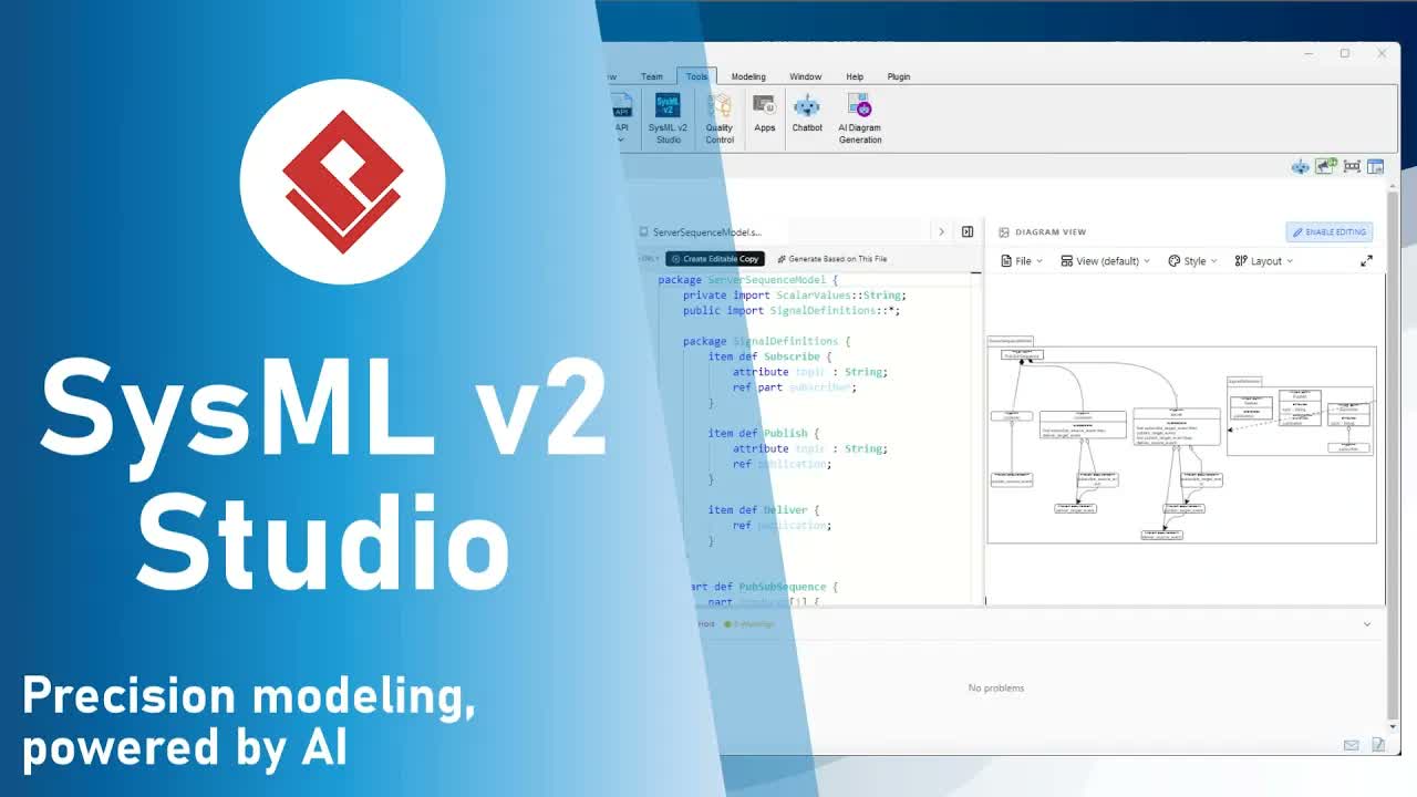
In systems engineering, a model is only as powerful as its ability to communicate. While a SysML 2 tool must prioritize mathematical and logical rigor, it must also provide intuitive presentation controls to make complex models accessible. A dense, tangled web of interconnections—no matter how technically accurate—fails if stakeholders cannot digest the information.
Visual Paradigm’s SysML 2 Studio bridges the gap between technical precision and visual clarity. With advanced presentation controls, this SysML 2 IDE empowers systems engineers to tailor diagram layouts, connector styles, and narrative flows for technical audits or high-level executive reviews.
Why Visual Presentation Matters in Systems Engineering
Engineers often deal with large-scale architectural views containing hundreds of ports, parts, and connections. SysML 2 Studio’s visualization engine enables you to “untangle” these complex relationships through controlled flows, clear routing, and high-resolution exports.
Key Presentation Controls in SysML 2 Studio:
- Layout Direction: Control the narrative flow of your diagrams to suit hierarchical breakdowns or process-oriented sequences.
- Line Styles: Route connectors cleanly using orthogonal, curved, or polyline styles to reduce visual clutter.
- Seamless Navigation: Deep-zoom into specific ports with crisp label rendering and smooth canvas panning.
- High-Resolution Exporting: Output publication-ready diagrams for technical documentation, management reports, and slide decks.
Choosing the Right Layout Direction
The visual narrative of your system model depends on what aspect you want to emphasize:
| Layout Direction | Best Used For | System Engineering Application |
|---|---|---|
| Top-to-Bottom (Default) | Hierarchical decomposition and tree structures. | Showing how high-level systems break down into subsystems and components. |
| Left-to-Right | Process-oriented flows and sequence diagrams. | Visualizing wide horizontal architectures, data pipelines, and parallel components. |
Step-by-Step: Customizing Your Diagram in SysML 2 Studio
Follow these quick steps to polish your SysML 2 diagram layout using our built-in training example:
- Open the Target SysML Model:In the Examples pane, open
Training 011 Connections 06 Hospital Gas Delivery.sysml. - Change Connector Line Style:On the top menu of the diagram viewer, select Layout > Line Style > Orthogonal. Notice how the connectors immediately align into clean, readable right-angled paths.
- Reorient Diagram Layout Direction:Select Layout > Direction > Left to Right. Watch the system architecture automatically reorient itself into a horizontal flow.
- Navigate & Zoom into Detail:Press and hold the Ctrl key on your keyboard while scrolling your mouse wheel to zoom in on specific ports. Notice that all text labels remain perfectly crisp. Use the mouse button to click and drag (pan) across the canvas smoothly.
- Export High-Resolution Image:Once your diagram is perfectly formatted, navigate to File > Export as PNG to save a clean, high-resolution graphic for your reports or presentations.
Frequently Asked Questions (FAQ)
Why should I change line styles in SysML 2 diagrams?
Line styles such as orthogonal or polyline prevent overlapping connector lines, drastically reducing visual noise in complex system architecture diagrams.
Can I export SysML 2 diagrams without losing visual quality?
Yes. SysML 2 Studio allows you to export customized views directly as high-resolution PNG images, preserving vector-level clarity for external documentation and slide decks.