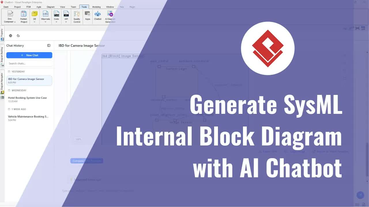
Visualizing the physical or logical organization of software modules is essential for software architecture, system design, and technical design reviews. While high-level architecture models outline system boundaries, capturing component interfaces, provided and required ports, and structural dependencies requires a detailed component view. A UML Component Diagram provides this structural clarity by mapping out software modules and how they connect to form larger systems.
With Visual Paradigm, software architects and developers can move past manual diagram creation. By utilizing AI-powered diagram automation, you can transform simple text prompts into clean, professional component architecture models instantly.
What is a UML Component Diagram?
A Unified Modeling Language (UML) Component Diagram is a structural diagram that shows how components are wired together to form larger software systems or subsystem architectures. It highlights software components, their internal structure, provided and required interfaces, ports, and execution dependencies. This offers engineering teams a clear blueprint for modular design, component reusability, and software assembly.
Key Benefits of AI-Driven UML Component Diagramming
- Instant Structural Generation: Convert plain-text system architecture descriptions into detailed UML component views in seconds.
- Automated Dependency and Interface Mapping: Automatically identify and render component interfaces, ports, and inter-component dependencies without manual connector routing.
- Clear Architecture Reviews: Present well-structured models during design reviews to align developers, architects, and technical leaders on system boundaries.
- Standardized Visual Specs: Maintain uniform UML 2.x standard notation across enterprise system specifications and development documentation.
Common Practical Use Cases
- Enterprise Software Frameworks: Map out relationships between user interface modules, core business logic components, and database access libraries.
- Service-Oriented Architectures (SOA): Detail service components, exposed public interfaces, and dependency links across backend application layers.
- Embedded Systems Design: Visualize hardware-software component boundaries, input/output ports, and driver dependencies in complex embedded software systems.
Step-by-Step Guide: Creating UML Component Diagrams from Text Prompts
- Describe Your System Architecture: Write a concise narrative describing the main components, provided/required interfaces, ports, and dependencies in your software system.
- Open the AI Diagram Tool: Access the AI generation feature inside the Visual Paradigm Download application.
- Input Your Text Description: Enter your system prompt into the designated AI text prompt field.
- Generate the Diagram: Allow the AI engine to automatically construct component blocks, interface nodes, ports, and dependency connections.
- Refine and Export: Fine-tune component arrangements, verify interface labels, and integrate the final model into your project documentation hub.
Elevate Your Software Architecture Modeling Today
Streamline component design and bring clarity to complex software architectures effortlessly. Design diagrams online in your browser using Visual Paradigm Online, centralize software specifications in the OpenDocs Editor, or explore interactive modeling assistance through the AI Chatbot Tool to scale your engineering workflow.