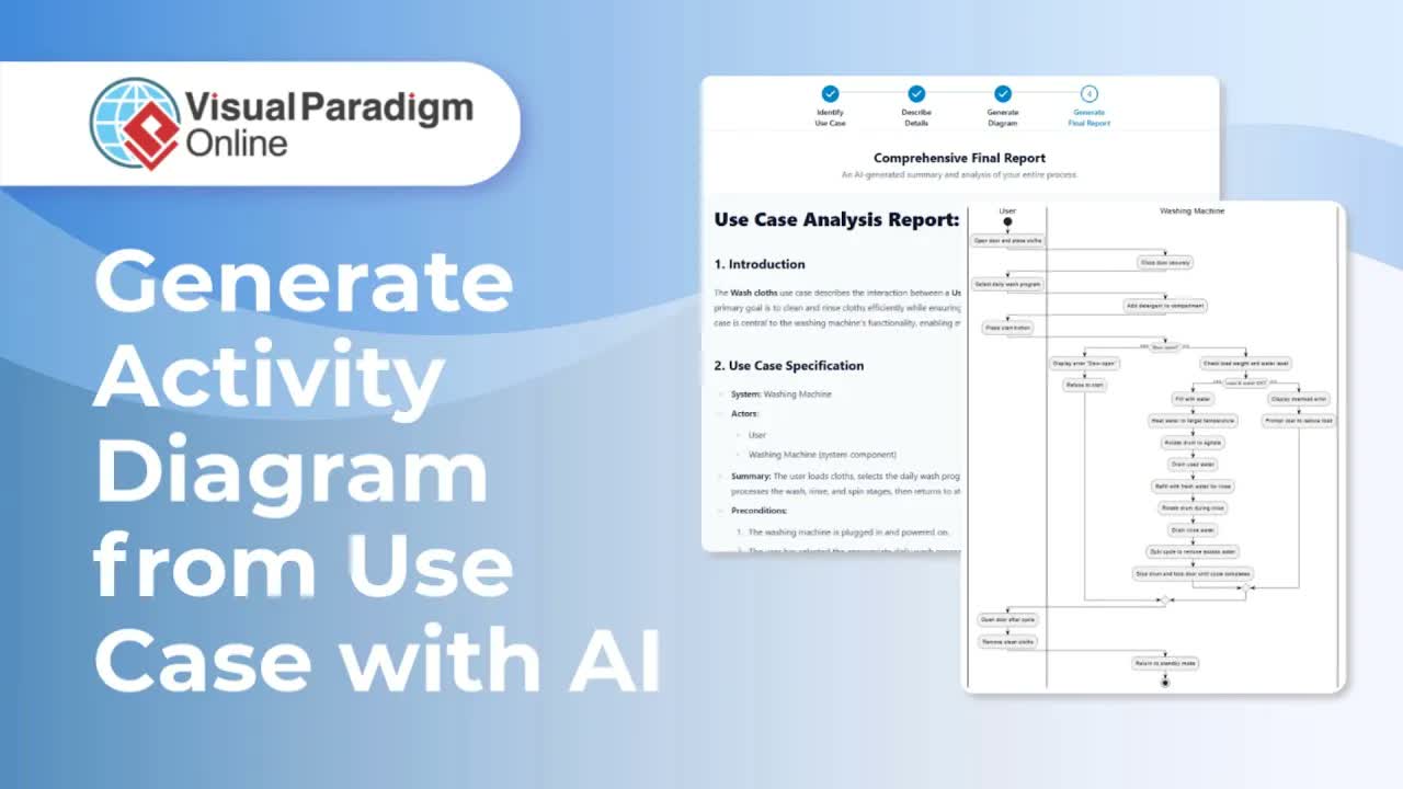
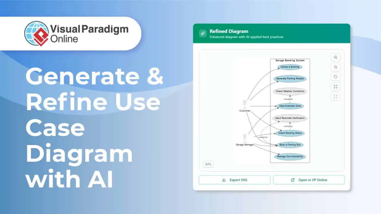
UML Use Case Diagrams are essential visual models for capturing functional requirements, identifying actors, and mapping system interactions using Visual Paradigm Online.
This comprehensive guide details how to build Use Case Diagrams using both reusable component workflows and direct single-page insertion, leveraging AI assistance to accelerate system design and technical documentation.
Understanding Use Case Diagrams in OpenDocs
Defining user goals and system boundaries through text alone can lead to ambiguous requirements. The OpenDocs environment integrates UML modeling tools directly inside your document workspace, eliminating the need to export static graphics or rely on disconnected software.
With the OpenDocs Editor, you can construct Use Case Diagrams manually from scratch or generate complete initial layouts automatically using AI. OpenDocs also supports component-based modeling, allowing a single master Use Case Diagram to be saved as a reusable asset and embedded across multiple documentation pages.
Key Benefits & Features
- AI-Powered Diagram Generation: Draft complete actor-system interactions, use case boundaries, and relationships instantly using natural language prompts.
- Reusable Component Pages: Store Use Case Diagrams as standalone assets and insert them across multiple pages or chapters in your knowledge base.
- Granular Structural Customization: Easily add actors, fine-tune use case goals, and organize association lines.
- Unified Requirements Specifications: Keep visual use case models tightly bound with written functional requirements and user story documentation.
Method 1: Creating a Reusable Use Case Diagram Component
When a use case model needs to be referenced across multiple chapters or system requirement pages, creating a reusable component page is the recommended approach.
Step 1: Build and Design the Reusable Diagram
- In your document tree or node view, click the Plus (+) icon on a node and select New Component Page. A new diagram component will be created as a child of that node.
- When prompted for the diagram type, select Use Case Diagram to open the editor.
- Construct Manually or with AI:
- Manual Construction: Build the diagram from scratch by adding system boundaries, actors, and use case ovals manually.
- AI Generation: Click Create with AI at the top right to let AI generate the diagram for you. Note: Using AI generation will erase any existing content in the diagram.
- Refine the actors, use cases, and relationships until the model accurately reflects your system scope.
- Click Save at the top right, then click the Left Arrow to close the editor. Your diagram is now stored as a reusable component.
Step 2: Insert the Saved Diagram into Any Page
- Open the target page in edit mode and click Insert.
- Choose Diagram, then select Import Existing.
- Select your use case diagram and insert it into the page.
Method 2: Creating a Single-Page Use Case Diagram
If a Use Case Diagram does not need to be reused elsewhere, you can create it directly inside that page layout.
Step-by-Step Instructions:
- Open the desired page in edit mode.
- Go to Insert, choose Diagrams, and select Use Case Diagram.
- The editor will open directly over your page layout.
- Build the diagram manually or generate it with AI.
- Tweak and refine the layout as needed.
- Click Save and close the editor to display the use case diagram right inside your page.
Practical Applications for Technical Teams
Embedding Use Case Diagrams directly into live technical documentation enhances project scope alignment across organizations:
- Systems Analysts & Product Owners: Define user roles, system boundaries, and core feature goals alongside functional requirement specifications.
- Software Engineers & Architects: Model primary actor interactions and system integrations. Developers writing custom automation code can also leverage VPasCode or the web-based VPasCode Editor.
- Quality Assurance & Testing Teams: Validate test scenario coverage against mapped use case flows. Teams can also integrate an AI Chatbot Tool or deploy an interactive Chatbot interface to assist stakeholders querying software specifications.
Streamline Your Requirements Modeling Today
Combining AI-assisted use case generation with dynamic document publishing ensures your team documents user interactions accurately. Explore the full suite of visual modeling tools powered by Visual Paradigm to elevate your documentation workflow today.